Meshes
All outcrop models are loaded as “meshes”. Meshes contain the 3D coordinate of each point on the face of the outcrop and information on how those points are connected to form the face of the outcrop (triangulation). In addition, meshes (also known as models) contain information on the color of each point or provides reference to images (known as textures) that color the face from photographic elements. Textures are usually supplied as picture (e.g., jpeg or png) files.
OpenOutcrop supports two common mesh formats. There are –
· Wavefront Object files (*.obj)
· Stanford poly file format (*.ply)
Great effort has been expended in ensuring that many variants of ply and obj files can be loaded. While. ply and .obj files are predominant, other formats can be added on request if the demand is great enough.
Meshes MUST reference a local coordinate system as coordinates within OpenOutcrop are stored as to be accurate to only 6 significant digits to minimize the amount of data stored on the graphics card (using 32-bit floating point coordinates). An XY coordinate range of +/- 1000m will result in coordinates being stored to single cm accuracy. To georeference coordinates to (say) UTM use the project properties screen to add in the appropriate offset to (say) UTM coordinates. Alternatively, you can click on the main menu item “Edit/Project properties…”
OpenOutcrop allows multiple models (meshes) to be present in
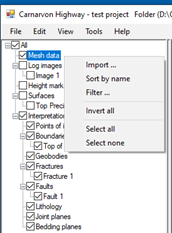
a project. To import new meshes into a new or existing project, simply right
click on the node labelled “Mesh data” in left hand panel of the screen as
below, and select Import…
Depending on the size of the imported mesh, this operation may take some time. Note also that multiple models can be loaded at the same time by selecting more than one file at a time.
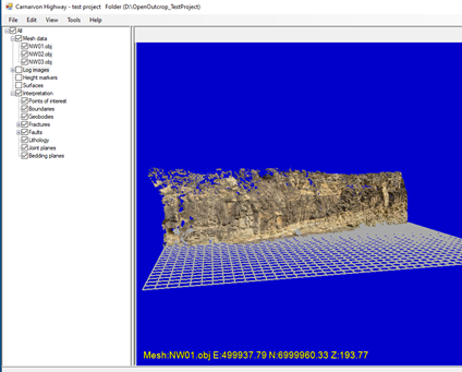
Once loaded, the model (or models) will be displayed on the screen. For example –
Things to do with meshes
When a mesh is selected the
properties are displayed in the panel at the top right-hand corner of the
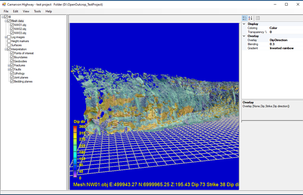
screen. The entries that are not dimmed (read only) can be changed to recolor
or redisplay the selected mesh in other ways. For example, changing the overlay
type to “Dip Direction” will result in the following –
A note about the calculation of
Dip and Strike
Dip and strikes are
calculated for each triangle vertex in the triangulated model. For each vertex, OpenOutcrop finds all
connected vertices to calculate a least squares plane. The dip and strike are derived
from each plane. For an understanding of the method used, please refer to https://www.tjscientific.com/2017/08/16/computationally-calculating-strike-and-dip-from-3-points/
As the calculation is highly localized,
we can infer that the dip direction (of the outcrop face) is equivalent to the localized
outcrop face dip.
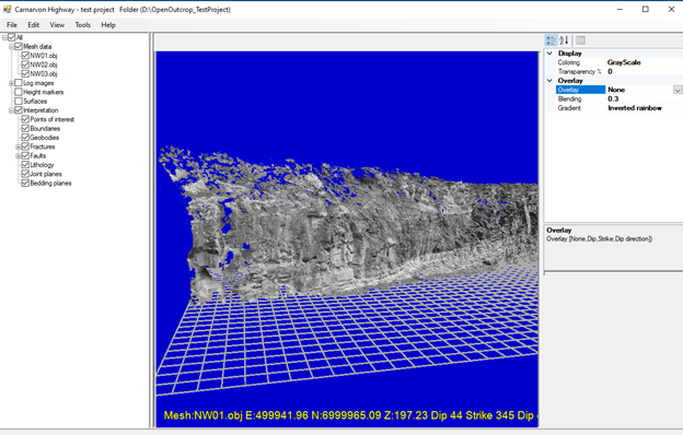
Alternatively, setting the
overlay type back to “None” and changing “Color” to “GrayScale” results in the
following.
If there are multiple
models/meshes displayed, you can apply the same properties to all meshes by
simply clicking on the “Mesh data” node and changing the display properties in
the RH screen, viz -
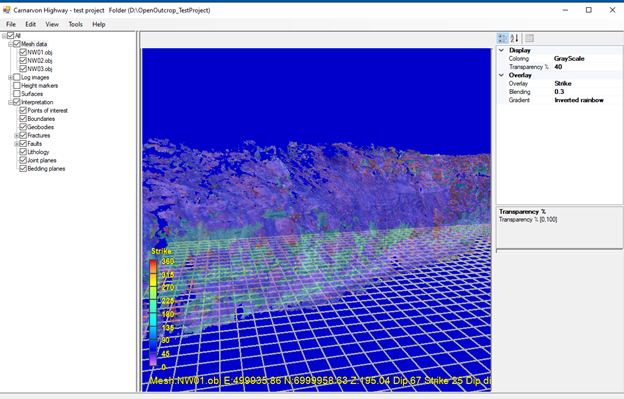
Note also in the above the
current world coordinate, dip, strike and dip direction are shown for the
current location of the mouse cursor.
We can also change the
transparency of meshes to, say, 20% and as a result some of the grid lines can
be seen “through” the image.
The “transparency” property
can be useful if you have multiple meshes (say on both sides of a road cutting)
to compare boundary interpretations on both sides of the outcrop.